35 MPa Hydrogen Compressor
Product Information
System rated working pressure:
105 megapascals
maximum booster pump discharge pressure listed:
15,000 psi
Listed output flow:
Over 370 NL/min
air consumption:
≥3.5 Nm³/min
Pressure measurement accuracy:
±0.5% full scale


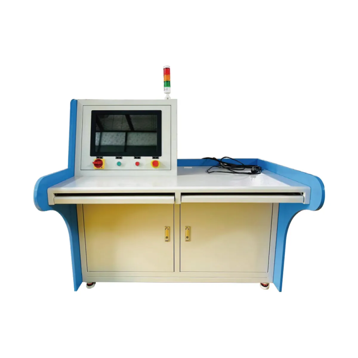
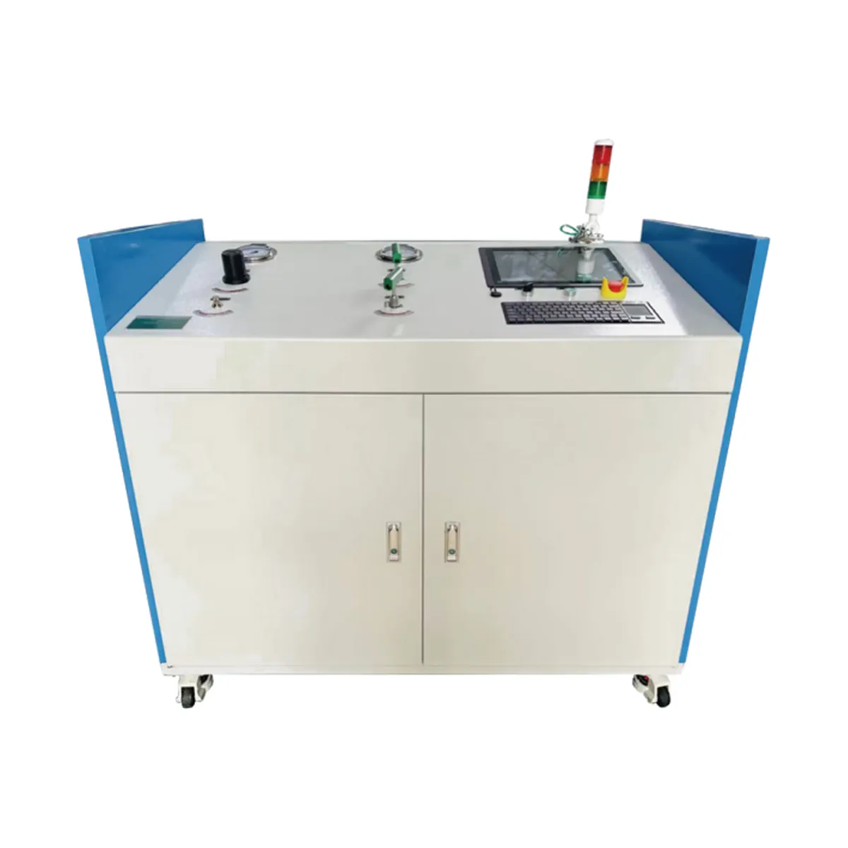
This hydrogen booster system provides high-pressure hydrogen to downstream equipment that performs cyclic testing of combination valves for hydrogen storage cylinders. The unit integrates a booster system, hydrogen cooling, control piping, and system controls. A single high-pressure outlet provides the connection to the test bench.
For valve manufacturers, laboratories, and equipment integrators, the unit defines the gas supply scope within the test facility. When specifying the unit, provide the bench’s required inlet pressure, gas flow, and temperature throughout the test cycle.
Integrated Gas Delivery and Cooling System
The system increases the inlet hydrogen pressure according to the selected test parameters. Its cooling section is integrated into the gas supply unit. If your test method specifies a gas temperature at the sample, include that target value and the measurement location in your inquiry.
This configuration uses compressed air as the power source for the booster pump and a high-pressure hydrogen cylinder bank as the gas supply. Separately specify the available air pressure and flow rate from the gas supply pressure. This helps define the unit and its connections to the facility.
Technical Specifications
| Parameter | Specification |
| Test medium | Hydrogen, nitrogen, and helium |
| Rated system operating pressure | 105 MPa |
| Safety valve opening pressure | 120 MPa |
| Booster pump | 2 units |
| Maximum booster pump output pressure | 15,000 psi |
| Output flow | Greater than 370 NL/min |
| Compressed air supply pressure | 0.7–0.8 MPa |
| Compressed air flow requirement | ≥3.5 Nm³/min |
| Gas outlet | 1 high-pressure outlet |
| Pressure measurement accuracy | ±0.5% full scale |
| Explosion protection rating | Ex d IIC T5 |
Confirm the outlet pressure for the selected configuration
The equipment list specifies 105 MPa as the system operating pressure and 120 MPa as the safety valve opening pressure. It separately lists a maximum booster pump output pressure of 15,000 psi, equivalent to approximately 103.4 MPa.
Because the listed maximum pressure of the booster pump is lower than the listed system operating pressure, please request written confirmation of the selected booster pump model and achievable outlet pressure before specifying the unit for 105 MPa operation. For projects with hazardous area requirements, please also request documentation and scope for the listed explosion protection rating.
Check flow rate against the bench’s cycle demand
The specification lists an output flow rate greater than 370 NL/min. For sizing, provide the required flow rate at the actual discharge pressure, along with gas type, inlet pressure, and temperature. Request the supplier to confirm the flow rate basis and achievable delivery capacity under these conditions.
If the test bench draws gas intermittently, please include peak demand and time between cycles. Also provide the mating connection dimensions and any pressure variation limits at the bench inlet. These details help align the gas supply with the test sequence.
Request a Hydrogen Booster System Quotation
Send us your required discharge pressure and flow rate, gas supply conditions, cooling target value, and valve cycle profile. Include available compressed air conditions, outlet connection drawings, and any control signals the test bench requires from the booster unit.
For procurement, please add installation location, inspection and documentation requirements, and target delivery date. Request an agreed performance point in the quotation so that engineering and procurement departments can review the same configuration.